QLD - Brisbane | Gold Coast | Sunshine Coast | Rockhampton | Mackay | Townsville | Cairns
NSW - Sydney | Regional & Northern NSW
Installation Manual -Clad Wall Guide for Residential Application
This guide is current at July 2017. ABSpanel has taken all reasonable care in producing this guide, but ABSpanel makes no representations or warranties, express or implied, as to the accuracy, reliability or completeness of the guide, and disclaims all liability, direct or indirect (and whether or not arising out of the negligence, default or lack of care of ABSpanel) for any loss or damage (whether foreseeable or not) suffered by the recipient or any other person arising out of, or in connection with, any use or reliance by any of them on the guide. Liability which cannot legally be excluded is limited to the maximum extent possible.
Information including acoustic and fire rating has been sourced from recognised third parties. Systems, standards and building codes are subjected to change. It remains the responsibility of the building designer to verify these systems are suitable for the particular requirements of any given project
Information including acoustic and fire rating has been sourced from recognised third parties. Systems, standards and building codes are subjected to change. It remains the responsibility of the building designer to verify these systems are suitable for the particular requirements of any given project
1. Typical Application
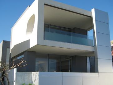
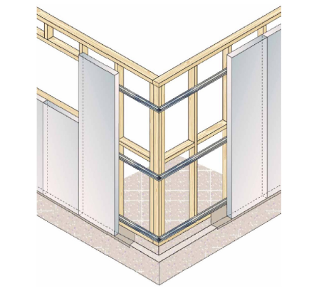
ABSpanel Clad Wall is designed for application in the domestic residential markets. Basically the types of buildings that are constructed using ABSpanel Clad Wall are detached or attached 1 or 2 storey houses, duplexes and town houses. The BCA generally classifies these buildings as being predominantly of Class 1 or Class 10 building structures. Structurally, ABSpanel Clad Wall uses the panel as non-load bearing external cladding. Each panel is installed vertically and secured to steel top hats or battens. The top hats or battens are secured to a load carrying timber or steel stud frames. Other complementary systems that can be used in conjunction with ABSpanel Clad Wall is the ABSpanel flooring which can be quickly installed over timber or steel floor framing using a construction adhesive & screw fixings. For more information regarding these systems please email [email protected]
2. How To Design An ABSpanel Clad Wall
2.1 Design Process:
This section outlines the design process for determining the adequacy of ABSpanel Clad Wall. Steps:
1) Determine the wind category, stud framing layout and panel height requirements.
2) Design Criteria. Where required identify the BCA Performance Requirements:
- Fire Resistance Level (FRL).
- Sound insulation performance (Rw, Ctr values). o Energy Efficiency (R-Value).
3) Select a type, spacing and quantity of top hats and fixings to suit requirements.
4) Select insulation and/or sarking material to suit energy efficiency and
5) condensation requirements.
6) Check adequacy of sound insulation, fire resistance level.
7) Complete detailed design and documentation.
2.2 Compliance with the Building Code of Australia (BCA)
All building solutions, such as walls, floors, ceilings, etc. must comply with the regulations outlined in the Building Code of Australia (BCA) or other authority. The BCA is a performance based document, and is available in two volumes which align with two groups of ‘Class of Building’: Volume 1 - Class 2 to Class 9 Buildings; and Volume 2 - Class 1 & Class 10 Buildings – Housing Provisions.
Each volume presents regulatory Performance Requirements for different Building Solutions for various classes of buildings and
performance provisions. These Performance Provisions include: Structure, Fire Resistance, Damp & Weatherproofing, Sound Transmission& Insulation, and Energy Efficiency. The designer must check the adequacy of the building solution for Performance Requirements outlined by the appropriate authority.
DETERMINE - Wind category
CONFIRM - Stud capacity and spacing
ESTABLISH - Panel height from design Stud capacity and spacing
DETERMINE - No. of Top hats | Max. spacing | No. of screws | Corner effects | Control Joint layout.
2.3 Overview
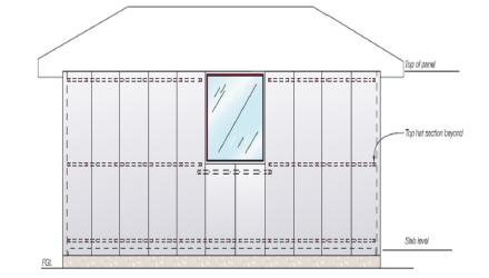
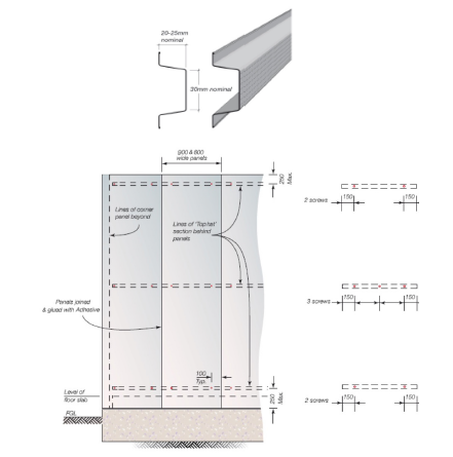
ABSpanel Wall Clad basically consists of a panel secured to the framing via horizontal steel top hats. Basic information on the selection of top hat spacing for a given stud spacing and wind category, as well as considerations to assist the designer in determining the appropriate wall configuration is attached in the Technical Drawings.
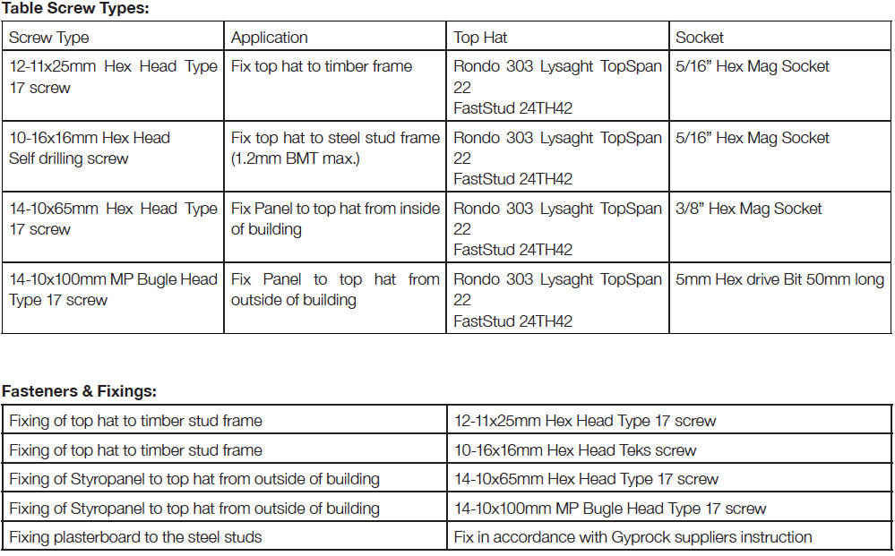
The design information presented has been determined for the following top hat types:
IMPORTANT
The design and approval of the structural framing (cold-formed steel or timber) is to be provided by the framing product manufacturer and/or project engineer.
This section outlines the design process for determining the adequacy of ABSpanel Clad Wall. Steps:
1) Determine the wind category, stud framing layout and panel height requirements.
2) Design Criteria. Where required identify the BCA Performance Requirements:
- Fire Resistance Level (FRL).
- Sound insulation performance (Rw, Ctr values). o Energy Efficiency (R-Value).
3) Select a type, spacing and quantity of top hats and fixings to suit requirements.
4) Select insulation and/or sarking material to suit energy efficiency and
5) condensation requirements.
6) Check adequacy of sound insulation, fire resistance level.
7) Complete detailed design and documentation.
2.2 Compliance with the Building Code of Australia (BCA)
All building solutions, such as walls, floors, ceilings, etc. must comply with the regulations outlined in the Building Code of Australia (BCA) or other authority. The BCA is a performance based document, and is available in two volumes which align with two groups of ‘Class of Building’: Volume 1 - Class 2 to Class 9 Buildings; and Volume 2 - Class 1 & Class 10 Buildings – Housing Provisions.
Each volume presents regulatory Performance Requirements for different Building Solutions for various classes of buildings and
performance provisions. These Performance Provisions include: Structure, Fire Resistance, Damp & Weatherproofing, Sound Transmission& Insulation, and Energy Efficiency. The designer must check the adequacy of the building solution for Performance Requirements outlined by the appropriate authority.
DETERMINE - Wind category
CONFIRM - Stud capacity and spacing
ESTABLISH - Panel height from design Stud capacity and spacing
DETERMINE - No. of Top hats | Max. spacing | No. of screws | Corner effects | Control Joint layout.
2.3 Overview
ABSpanel Wall Clad basically consists of a panel secured to the framing via horizontal steel top hats. Basic information on the selection of top hat spacing for a given stud spacing and wind category, as well as considerations to assist the designer in determining the appropriate wall configuration is attached in the Technical Drawings.
The design information presented has been determined for the following top hat types:
- Rondo 303 – Rondo Building Services Pty Ltd.
- Lysaght Topspan 22 – Blue Scope Steel Ltd.
- FastStud 24TH42.
IMPORTANT
The design and approval of the structural framing (cold-formed steel or timber) is to be provided by the framing product manufacturer and/or project engineer.
3. Principles Of Design
The principles on which the design is based include:
a) The lateral wind loads applied to the panels are directly transferred to the stud frame, which should be designed in accordance with the relevant Australian Standards for the imposed loads. The frame should be designed for all bracing and hold down requirements.
b) The design of the stud frame shall consider the weight of suspended panels (such as the upper storey of two-storey construction).
c) The system is not considered as cavity construction, as the top hat clearly bridges the cavity, hence the details show the necessity of sealing the windows and door frames, as well as applying a water resistant external coating.
d) The system specifications vary with wind load. The notation used in AS1684-1999 Residential Timber Framed Construction has been adopted.
e) The localised effects of wind around corners of buildings have been considered in the design and included.
Criteria for Corner Panels - Due to the increase of wind load around the corners of buildings; extra top hats and screws may be necessary (N3 and greater) for a distance of 20% of the wall length in each direction from the corner.
Cyclonic Loading Effects - ABSpanel has been tested at the UNSW. The pullout capacity of the screw into the back of the panel is the critical element in the design. The results from the testing showed that the system, in particular the pullout load of the screw, is unaffected by the cyclic loading. The detailing presented in this design manual is satisfactory for cyclonic areas.
Earthquake Loads - Earthquake loading has not been considered in this design manual.
Note:
3.1 Stud Frame
The stud frame shall be designed by the steel stud manufacturer or appropriate project engineer. ABSpanel is a masonry product and the support structure should be designed to provide sufficient stiffness. The steel stud frame shall be designed and constructed in accordance with AS3623 or AS/NZS4600 (BCA Performance Requirement) with performance requirements for the studs of:
Properties - Cold-formed steel studs. Minimum yield strength 275MPa. Minimum thickness 0.75mm BMT. Coating class Z275. The designer shall specify the need for noggins.
3.2 Steel Top Hat
Steel top hats other than those referenced in this design manual shall be designed by the top hat manufacturer or appropriate project engineer. The steel top hats shall be designed and constructed in accordance with AS3623 or AS/NZS4600 (BCA Performance Requirement) with performance requirements for the top hats, of:
Properties - Cold-formed steel top hats. Minimum thickness 0.42mm BMT. Minimum yield strength 300MPa. Coating class Z275 (see Durability). Alternate steel top hats must have an equivalent or better performance than the top hat products outlined.
3.3 ABSpanel
Design procedures for the verification of wall systems consisting of ABSpanel generally follow the design principles outlined in Australian Standard AS3600: 2001 – Concrete Structures, with the exception of cover requirements for durability and development length for reinforcement. The strength design of the BSpanel has been carried out using the Transformed Section Theory. The load carrying capacity of the panel is influenced by several factors, such as:
Minimum screw coating class in accordance with AS3566: Class 3.
a) The lateral wind loads applied to the panels are directly transferred to the stud frame, which should be designed in accordance with the relevant Australian Standards for the imposed loads. The frame should be designed for all bracing and hold down requirements.
b) The design of the stud frame shall consider the weight of suspended panels (such as the upper storey of two-storey construction).
c) The system is not considered as cavity construction, as the top hat clearly bridges the cavity, hence the details show the necessity of sealing the windows and door frames, as well as applying a water resistant external coating.
d) The system specifications vary with wind load. The notation used in AS1684-1999 Residential Timber Framed Construction has been adopted.
e) The localised effects of wind around corners of buildings have been considered in the design and included.
Criteria for Corner Panels - Due to the increase of wind load around the corners of buildings; extra top hats and screws may be necessary (N3 and greater) for a distance of 20% of the wall length in each direction from the corner.
Cyclonic Loading Effects - ABSpanel has been tested at the UNSW. The pullout capacity of the screw into the back of the panel is the critical element in the design. The results from the testing showed that the system, in particular the pullout load of the screw, is unaffected by the cyclic loading. The detailing presented in this design manual is satisfactory for cyclonic areas.
Earthquake Loads - Earthquake loading has not been considered in this design manual.
Note:
- Figures shown in brackets are the top hats required when using RONDO 303 top hats.
- All top hats to be spaced evenly, with top and bottom top hats installed 150mm (typical) from the end of the panel.
- Additional top hats will be required below all window openings and above openings if a panel or sill block is to be installed in this location.
- Corner panels apply to panels within 1200mm of corners. Permissible wind pressures have been increased by a factor of 2 in these panel locations.
3.1 Stud Frame
The stud frame shall be designed by the steel stud manufacturer or appropriate project engineer. ABSpanel is a masonry product and the support structure should be designed to provide sufficient stiffness. The steel stud frame shall be designed and constructed in accordance with AS3623 or AS/NZS4600 (BCA Performance Requirement) with performance requirements for the studs of:
Properties - Cold-formed steel studs. Minimum yield strength 275MPa. Minimum thickness 0.75mm BMT. Coating class Z275. The designer shall specify the need for noggins.
3.2 Steel Top Hat
Steel top hats other than those referenced in this design manual shall be designed by the top hat manufacturer or appropriate project engineer. The steel top hats shall be designed and constructed in accordance with AS3623 or AS/NZS4600 (BCA Performance Requirement) with performance requirements for the top hats, of:
Properties - Cold-formed steel top hats. Minimum thickness 0.42mm BMT. Minimum yield strength 300MPa. Coating class Z275 (see Durability). Alternate steel top hats must have an equivalent or better performance than the top hat products outlined.
3.3 ABSpanel
Design procedures for the verification of wall systems consisting of ABSpanel generally follow the design principles outlined in Australian Standard AS3600: 2001 – Concrete Structures, with the exception of cover requirements for durability and development length for reinforcement. The strength design of the BSpanel has been carried out using the Transformed Section Theory. The load carrying capacity of the panel is influenced by several factors, such as:
- Imposed action (wind). Lateral stiffness of the supporting structure (lightweight structural (cold-formed) steel framing).
- Stud size and spacing.
- Deflection limit.
- Height of the wall.
- Number and spacing of the top hats.
- Number of screw fixings considered effective.
Minimum screw coating class in accordance with AS3566: Class 3.
Note:
- Number of top hats and top hat spacing to be confirmed by the building designer.
- Additional top hats may be required.
- ABSpanel has not setout top hats to accommodate control joint locations. This is the responsibility of the building designer.
4. Design Considerations
4.1 Structural Framing Design
The use of ABSpanel Clad Wall in two storey construction involves a number of design issues that require attention. In conjunction with the following, refer to the Construction Details.
Note:
When panels are suspended from the stud frame the project engineer shall design the frame to support the weight of the panels.
Design Tip:
In order to reduce the load of the upper storey panels and make installation easier, the lower storey panels should be specified as 2700mm/3000mm in length and the upper storey panels as 2400mm in length. The vertical dimensions can be adjusted to suit. A garage is considered ‘attached’ when at least one full side of the garage is connected to the main dwelling.
4.2 Two Storey Construction
Steel Frame Construction:
Two storey construction suits steel framed dwelling as the weight of the upper storey panels bear directly on the lower storey panels.
Note:
Lower storey panels are to bear on the slab. However consideration should be given to the sectional size of the lintels over openings on the lower storey. Only an ‘Able flex’ joint is required at the horizontal panel junction between the upper and lower panels.
Timber Frame Construction:
In contrast, due to the effects of timber shrinkage, movements in the order of 25mm can occur in a two storey timber frame with a timber first floor. The fixing method used in ABSpanel Clad Wall does not allow for this extent of differential movement between the external skin and the timber frame. It is therefore recommended that the upper storey panels be installed 35mm clear of the lower storey panels. During construction a temporary packer is used to separate the panels and is then removed after the panels have been screwed to the top hats. The impact of this construction is to load the lower storey frame with the weight of the upper storey panels. In effect, an extra 50kg/m2 (for the height of the upper panels) is being added to the load already carried by the timber frame. The load approximates 1.3 kN/m (2.4m panel). To simplify the design implications of this extra load, it is recommended to add an extra 1.5m of tributary width for a 90kg/m2 Tile Roof load (for 2.4m long upper panels) for the design of the lower storey frame and timber lintels, when using AS1684 -1999. The support of the full weight of the upper storey panels can be adequately supported by the top hat system. A full design using a safety factor of five has been undertaken and checked to confirm this. The number of top hat can be determined to support the suspended panels, and the panel's screw fixed.
4.3 Secondary Support Framing
There is a need for secondary support framing when: The layout of the main structural framing does not allow this framing to be used as a support. In this case a mullion is required to breakup the span of the panel, or cleats provided to act as support and connection points for the panels. Around openings: the panels adjacent to the opening may not have sufficient capacity or stiffness to resist the additional loads that are re- distributed from the opening and infill panels. In this case angles are required to transfer the loads from the opening (window) and infill panels back to the main structural framing.
Note: ABSpanel does not recommend fixing panel from the inside when sheet bracing is installed. If sheet bracing is used over steel or timber frame construction then increase the length of the screw by the thickness of the sheet bracing.
5. Durability
5.1 Overview
Durability means the capability of a building or its parts to perform a function over a specified period of time. It is not an inherent property of a material or component. It is the outcome of complex interactions among a number of factors, including:
(‘ABCB Guideline Document –Durability in buildings: 2003’)
The following sub-sections of the durability topic are written in order to provide general guidelines in how best to provide, enhance and maintain adequate durability of ABSpanel Wall Clad.
5.2 Maintenance and Enhancement of Durability
The durability of ABSpanel Clad Wall can be enhanced by periodic inspection and maintenance. Inspections should include examination of the coatings, flashings and sealants. Paint finishes must be maintained in accordance with the manufacturer’s recommendations. Any cracked and damaged finish or sealants, which would allow water ingress, must be repaired immediately by recoating or resealing the effected area. Any damaged flashings or panels must be repaired and left as close as for new work. The durability of the system can also be increased by using Class 4 fixings throughout, additional treatment of steelwork, and by painting all exposed sealants to the sealant manufacturer’s recommendations.
5.3 Coastal Areas
ABSpanel Clad Wall can be used in coastal areas with additional precautions to ensure salt does not build up on the surface of the wall. For buildings, which are 200m to 1000m from a shoreline or large expanse of salt water, such as, Swan River (west of the Narrows Bridge), Sydney Harbour (east of the Harbour Bridge or Spit Bridge), one of the following is required:
All horizontal and vertical movement joints must be appropriately caulked; or all walls must be sufficiently exposed from above so that rain can perform natural wash-down of the wall; or walls, which are protected by soffits above, must be washed down twice per year, to remove salt and debris build-up, particularly at the joints. In all cases, Class 4 screws must be used. For buildings less than 200m from the shoreline as defined above, Absolute Building Supplies does not recommend that ABSpanel Wall Clad be used without project specific consultation with Engineer or Wall System Designer.
5.4 ABSpanel
ABSpanel has many characteristic which make it a very durable product, including: It will not rot or burn, it is not a food source for termites, and unaffected by sunlight. Not adversely affected over normal temperature ranges. It’s also one quarter of the weight of conventional concrete yet solid and strong.
5.5 Durability of Components
It is the responsibility of the building designer to ensure that the components, such as screws, top hat battens, and other steel components, have the appropriate corrosion protection to be able to maintain their strength and integrity to suit the required design life of the project.
IMPORTANT
The top hat section specified in this manual can ONLY be used on untreated and dry timber frames. CCA treated pine or green timber frames have a deleterious effect on the top hat coatings, which can lead to corrosion. Where timber is CCA treated, provide a barrier between top hat and timber member. Refer to screw manufacturer for appropriate screw specification for this application. When assessing durability the following documents can be referred to for guidance:
5.5.1 Wall Frames
Steel Frames
The designer needs to ensure that the steelwork and AAC products have adequate protective systems to ensure that durability is maintained. The durability of the stud frame can be enhanced by the provision of a membrane, such as sarking. The manufacturer of the steel stud frame can provide guidance on the appropriateness of this solution on a project-by-project basis.
IMPORTANT
The steel frame requirements outlined in the Building Code of Australia (BCA) Volume 2, Part 3.4.2 should be considered in conjunction with steel frame design and construction advice from the steel frame manufacturer. These requirements consist of minimum protective surface coatings with restrictions on the location of the building and exposure condition of the steel frame.
Timber Frames
Information on the durability design of timber structures and components can be obtained from documents such as: AS 1720.1 Timber structures, Part 1:Design Methods. AS 1684 Timber Framing Code. State timber framing manuals. AS 4100 Metal Connectors: Corrosion. AS 3600 Subterranean termites.
Top Hats
The top hats are used to fix the panel to the structural support framing. Three types of top hats can be used in the panel wall. These are Fast Stud 24TH42, Rondo No303, and Lysaght top span 22.
For alternative top hat types, the top hat manufacturer or project engineer will be responsible for approving the substitute product as adequate for performance requirements.
Durability means the capability of a building or its parts to perform a function over a specified period of time. It is not an inherent property of a material or component. It is the outcome of complex interactions among a number of factors, including:
- The service conditions
- Material characteristics
- Design and detailing
- Workmanship
- Maintenance
(‘ABCB Guideline Document –Durability in buildings: 2003’)
The following sub-sections of the durability topic are written in order to provide general guidelines in how best to provide, enhance and maintain adequate durability of ABSpanel Wall Clad.
5.2 Maintenance and Enhancement of Durability
The durability of ABSpanel Clad Wall can be enhanced by periodic inspection and maintenance. Inspections should include examination of the coatings, flashings and sealants. Paint finishes must be maintained in accordance with the manufacturer’s recommendations. Any cracked and damaged finish or sealants, which would allow water ingress, must be repaired immediately by recoating or resealing the effected area. Any damaged flashings or panels must be repaired and left as close as for new work. The durability of the system can also be increased by using Class 4 fixings throughout, additional treatment of steelwork, and by painting all exposed sealants to the sealant manufacturer’s recommendations.
5.3 Coastal Areas
ABSpanel Clad Wall can be used in coastal areas with additional precautions to ensure salt does not build up on the surface of the wall. For buildings, which are 200m to 1000m from a shoreline or large expanse of salt water, such as, Swan River (west of the Narrows Bridge), Sydney Harbour (east of the Harbour Bridge or Spit Bridge), one of the following is required:
All horizontal and vertical movement joints must be appropriately caulked; or all walls must be sufficiently exposed from above so that rain can perform natural wash-down of the wall; or walls, which are protected by soffits above, must be washed down twice per year, to remove salt and debris build-up, particularly at the joints. In all cases, Class 4 screws must be used. For buildings less than 200m from the shoreline as defined above, Absolute Building Supplies does not recommend that ABSpanel Wall Clad be used without project specific consultation with Engineer or Wall System Designer.
5.4 ABSpanel
ABSpanel has many characteristic which make it a very durable product, including: It will not rot or burn, it is not a food source for termites, and unaffected by sunlight. Not adversely affected over normal temperature ranges. It’s also one quarter of the weight of conventional concrete yet solid and strong.
5.5 Durability of Components
It is the responsibility of the building designer to ensure that the components, such as screws, top hat battens, and other steel components, have the appropriate corrosion protection to be able to maintain their strength and integrity to suit the required design life of the project.
IMPORTANT
The top hat section specified in this manual can ONLY be used on untreated and dry timber frames. CCA treated pine or green timber frames have a deleterious effect on the top hat coatings, which can lead to corrosion. Where timber is CCA treated, provide a barrier between top hat and timber member. Refer to screw manufacturer for appropriate screw specification for this application. When assessing durability the following documents can be referred to for guidance:
- ABCB Guideline Document – Durability in buildings: 2003
- S/NZS 2312: 2002 – Guide to the protection of structural steel against atmospheric corrosion by the use of protective coatings
- ISO 9223: 1992 – Corrosion of metals and alloys – Corrosivity of Atmosphere Classification
- AS3566: 2002 – Self drilling screws for the building and construction industries. AS2331 Series
- Reference to AS3566 should always be adhered to when selecting the screws corrosion resistance classification.
5.5.1 Wall Frames
Steel Frames
The designer needs to ensure that the steelwork and AAC products have adequate protective systems to ensure that durability is maintained. The durability of the stud frame can be enhanced by the provision of a membrane, such as sarking. The manufacturer of the steel stud frame can provide guidance on the appropriateness of this solution on a project-by-project basis.
IMPORTANT
The steel frame requirements outlined in the Building Code of Australia (BCA) Volume 2, Part 3.4.2 should be considered in conjunction with steel frame design and construction advice from the steel frame manufacturer. These requirements consist of minimum protective surface coatings with restrictions on the location of the building and exposure condition of the steel frame.
Timber Frames
Information on the durability design of timber structures and components can be obtained from documents such as: AS 1720.1 Timber structures, Part 1:Design Methods. AS 1684 Timber Framing Code. State timber framing manuals. AS 4100 Metal Connectors: Corrosion. AS 3600 Subterranean termites.
Top Hats
The top hats are used to fix the panel to the structural support framing. Three types of top hats can be used in the panel wall. These are Fast Stud 24TH42, Rondo No303, and Lysaght top span 22.
For alternative top hat types, the top hat manufacturer or project engineer will be responsible for approving the substitute product as adequate for performance requirements.
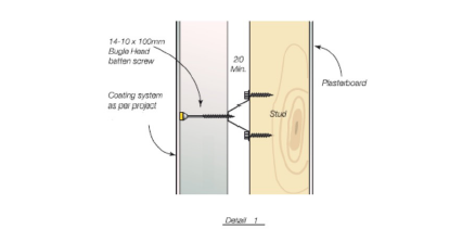
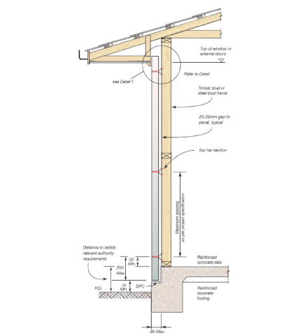
ABSpanel Clad Detail
6. Handling & Installation Guidelines
1. Introduction
In this document, ABSpanel will outline handling issues to be addressed during the panel installation. However, there is no replacement for common sense.
2. Panel Delivery and layout
When ABSpanels are delivery to site, it is recommended that the panels be taken from the truck to the appropriate work area. This will reduce the amount of double handling and product damage.
3. Layout Drawings
When layout drawings are provided, then the panels shall be installed as detailed on the drawings. The project engineer shall be consulted for prior approval of any variations. Panels should not be cut unless indicated on the Layout Drawings.
4. Site Preparation
The work area should be kept clear of waste and unnecessary equipment, and panels arranged to allow easy, unobstructed access to work area (eliminate possible tripping).
All preparation and accessories, such as brackets, fixings, adhesives, packers, surface treatments (waterproof membranes etc) should be accessible, installed or completed prior to lifting the panels.
5. Lifting
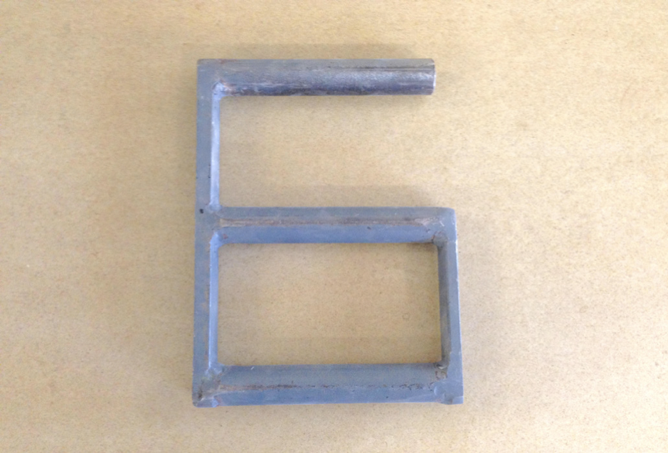
Whenever possible, panels are to be lifted and transported to the workplace using approved lifting devices.
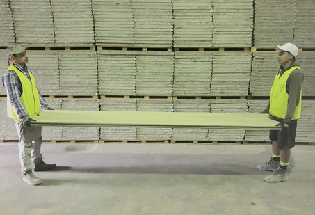
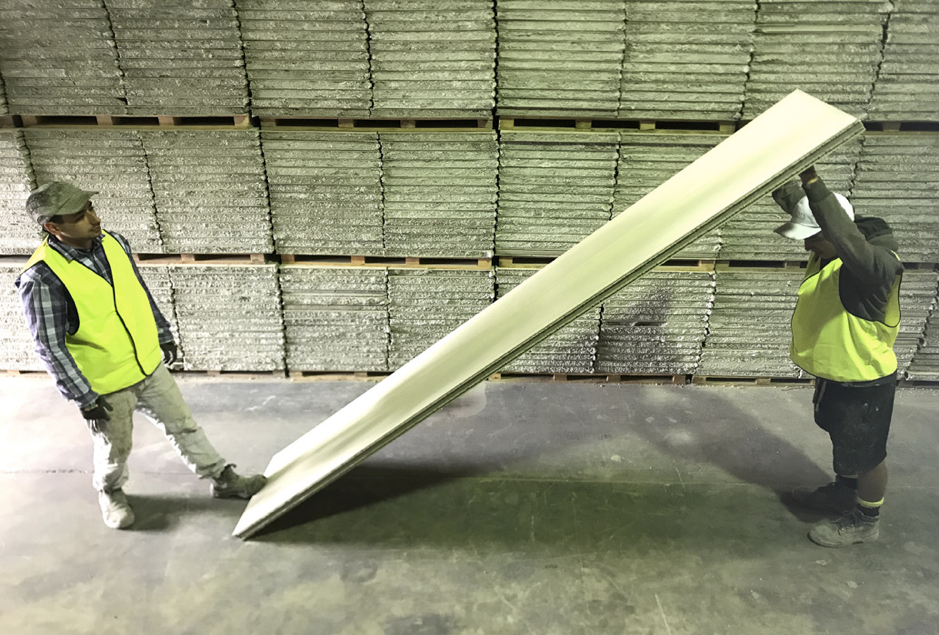
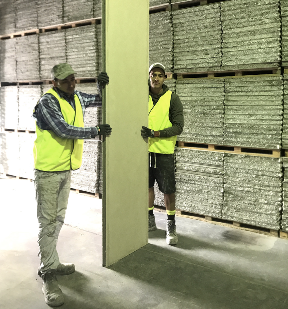
When lifters are to be used to lift and move the panels, ABSpanel recommends lifting them with your legs, keeping your back straight, and stabilising the panel with your shoulder and/or free hand. It is not recommended that the panel be held clear of the lifter’s body causing undue stress to the person lifting the panel.
During installation, persons not involved in the lifting and fixing process should remain clear of the work area, and make installlers aware of their presence before approaching.
IMPORTANT: Ensure every member of the installation team is aware of their role and that there is a nominated team leader.
6. Bracing
At all times, the panel should be supported by a person other than the person installing the fixings. Never release a panel until all fixings are installed and the panel is secure.
7. Recommended Panel Handling Guidelines
|
|
|
|
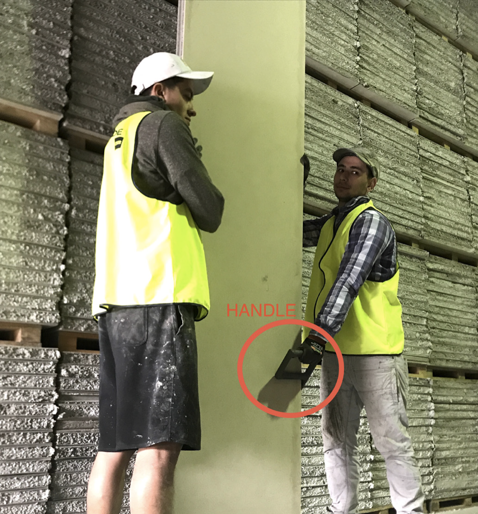
- Lifting handles are to be positioned so arms are straight when panel is lifted
- Bend your hips and knees and straighten your legs to lift
- Use your feet to change direction, taking small steps to place panel into position
8. Material Safety Data Sheet
IMPORTANT NOTICE:
This Material Safety Data Sheet (MSDS) is issued by the Supplier in accordance with National Occupational Health and Safety Commission (NOHSC) guidelines. As such, the information in it must not be altered, deleted or added to. The Supplier will issue a new MSDS when there is a change in product specifications and/or NOHSC guidelines/regulations. The Supplier will not accept any responsibility for any changes made to its MSDS by any other person or organisation.
This Material Safety Data Sheet (MSDS) is issued by the Supplier in accordance with National Occupational Health and Safety Commission (NOHSC) guidelines. As such, the information in it must not be altered, deleted or added to. The Supplier will issue a new MSDS when there is a change in product specifications and/or NOHSC guidelines/regulations. The Supplier will not accept any responsibility for any changes made to its MSDS by any other person or organisation.
Product Name: ABSpanel
Applicable In: Australia
Manufacturer's Product Code: Not Applicable
UN Number: None Allocated
Dangerous Goods Class & Subsidiary Risk: None Allocated
Hazchem Code: None Allocated
Poisons Schedule Number: None Scheduled
Physical Description/Properties: Lightweight concrete panel
Appearance: Grey flat sheets sandwiching a 50mm,75mm 0r 100mm thick polystyrene and cement mix
Boiling Point (oC): Not Determined
Melting Point (oC): Not applicable
Vapour Pressure: Not Determined
Specific Gravity (H20=1): 1.3 to 1.7
Flashpoint: Not Applicable
Flammability Limits: Not Flammable
Solubility In Water: Not Applicable
Use: Used as external & internal cladding for residential housing, commercial walling, industrial buildings and flooring. Also for inter-tenancy, FRL, party and any walling system for the above for load bearing and non load bearing wall applications.
NOTE:
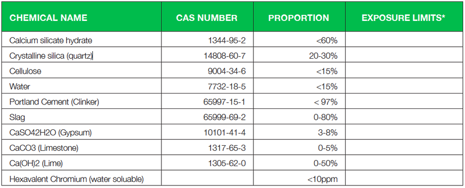
Some products are sealed with acrylic sealer and/ or coated with acrylic coatings. The proportion of these propriety coatings does not exceed 1%. All ingredients may contain crystalline silica. This product does not contain asbestos or asbestiform fragments. Cellulose comes from wood pulp.
HEALTH HAZARD INFORMATION
STATEMENT OF HAZARDOUS NATURE: This product is classified as hazardous according to the criteria of the National Occupational Health and Safety Commission (NOHSC).
HEALTH EFFECTS
ACUTE
Swallowed: Unlikely under normal conditions of use, but swallowing the dust from this product may result in abdominal discomfort.
Eye: The dust from this product may irritate the eyes causing watering and redness.
Skin: The dust from this product, particularly in association with heat and sweat, may cause irritation, but it is not absorbed through the skin.
Inhaled: The dust may cause irritation of the nose, throat and lungs.
CHRONIC
Inhaled: Repeated exposure to the dust may result in increased nasal and respiratory secretions and coughing. Because of the presence of respirable quartz (crystalline silica), repeated and prolonged exposure to high dust levels may result in silicosis and an increased risk of lung cancer. The International Agency for Research on Cancer (IARC) has evaluated crystalline silica as " Group 1 - Carcinogenic to humans".
Special Note: Based on limited animal research, it is possible that repeated inhalation of cellulose fibre dust over time may lead to inflammation and scarring of the lung in humans. Measures taken to protect against crystalline silica dust will also be adequate for preventing health effects from cellulose. See ‘Precautions for Use’.
FIRST AID
Swallowed: Rinse mouth and give plenty of water to drink. If symptoms persist seek medical attention.
Eye: Flush thoroughly with flowing water for at least ten minutes. If symptoms persist, seek medical attention.
Skin: Wash thoroughly with soap and water. If any irritation persists seek medical advice.
Inhaled: Remove too fresh air. Seek medical advice if symptoms persist.
Advice to Doctor: Treat symptomatically.
PRECAUTIONS FOR USE
EXPOSURE
Standards: None Allocated from NOHSC. There is no specific standard for Fibre Cement but the standards for calcium silicate containing <1.0% crystalline-silica and crystalline-silica (quartz) should apply. Respirable Silica-crystalline: 0.2 mg/cubic metre time-weighted average (TWA) Inspirable calcium silicate dust: 10.0 mg/ cubic metre time-weighted average (TWA). Cellulose (paper fibre): 10 mg/cubic metre (TWA) measured as inspirable dust.
Engineering Controls: During the normal installation of the product, no significant dust problem should occur. If, however, the product is cut or machined, the following precautions should be applied: Hand tools should be used for cutting, drilling or sanding. If the use of power tools is necessary, the power tools must be fitted with efficient and well maintained dust extraction devices. Work areas should be well ventilated and cleaned at least daily. Dust must be removed by vacuum cleaners fitted with HEPA filters, by sweeping after dampening, or by hosing if approved waste water collection systems are available.
Manufacturers’ Recommendations: Keep exposure of dust as low as practicable.
PERSONAL PROTECTION
Skin Protection: Loose comfortable clothing should be worn.
Approved personal protective equipment should conform with the relevant standards published by Standards Australia and/or Standards New Zealand. Direct skin contact should be avoided by wearing long sleeved shirts andlong trousers, a cap or hat, and gloves (standard duty leather or equivalent AS 2161). Work clothes should be washed regularly and separately from other clothes.
Eye Protection: Ventilated non-fogging goggles (dust resistant AS/NZS 1336) should be worn when working in a dusty environment.
Respiratory Protection: An approved particulate respirator (AS/NZS 1715 and 1716) should be worn when working in a dusty environment. Respirators should be correctly fitted, maintained in good condition, and kept in clean storage when not in use. Replaceable filters and cartridges should be replaced regularly in accordance with the manufacturers’ guidelines and AS/NZS 1715 and 1716.
Personal Hygiene: Wash face and hands before eating or drinking after handling this product.
Flammability: Avoid a build-up of dust and keep all storage and work areas well ventilated.
SAFE HANDLING INFORMATION
Storage and Transport: This product should be stored in a dry area. No special transport requirements are necessary.
Spills and disposal: Dust and waste should be cleaned up by bagging, wet sweeping and/or vacuuming. Waste should be placed into containers and disposed of as trade waste in accordance with local waste disposal authority guidelines.
Fire/explosion hazard: The product is non flammable. Extinguish with Carbon dioxide, water, foam or dry chemical as for surrounding materials.
Smoking and Other Dust: Inhalation of airborne particles from other sources, including those from cigarette smoke, may increase the risk of lung disease. Absolute Building Supplies recommends that all storage and work areas should be non-smoking zones, and other airborne contaminants be kept to a minimum.
ECOLOGICAL INFORMATION
The ingredients for this product are not harmful and no adverse environmental effects would be expected if this product were accidentally released in the water or soil. No harm to fish or wildlife would be caused by this product. It is recommended that all off cuts and waste be disposed of properly and be kept clear of areas leading to drains and waterways.
Whilst the information contained in this document is based on data which, to the best of our knowledge, was accurate and reliable at the time of preparation, no responsibility can be accepted by us for errors and omissions. The provision of this information should not be construed as a recommendation to use any of our products in violation of any patent rights or in breach of any statute or regulation. Users are advised to make their own determination as to the suitability of this information in relation to their particular purposes and specific circumstances.
Since the information contained in this document may be applied under conditions beyond our control, no responsibility can be accepted by us for any loss or damage caused by any person acting or refraining from action as a result of this information.
For further information on our ABS Panel please contact Absolute Building Supplies on Ph 0437 289282 or email [email protected]
ABOUT
|
CONTACT US
|
|


